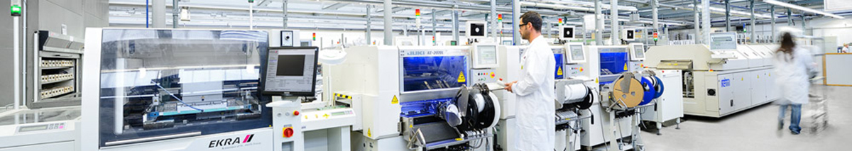
Reflow soldering is a process in which a solder paste (a sticky mixture of powdered solder and flux) is used to temporarily attach one or several electrical components to their contact pads, after which the entire assembly is subjected to controlled heat, which melts the solder, permanently connecting the joint. Heating may be accomplished by passing the assembly through a reflow oven or under an infrared lamp or by soldering individual joints with a hot air pencil.
Reflow soldering is the most common method of attaching surface mount components to a circuit board, although it can also be used for through-hole components by filling the holes with solder paste and inserting the component leads through the paste. Because wave soldering can be simpler and cheaper, reflow is not generally used on pure through-hole boards. When used on boards containing a mix of SMT and THT components, through-hole reflow allows the wave soldering step to be eliminated from the assembly process, potentially reducing assembly costs.
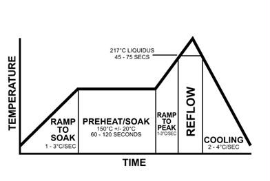
The goal of the reflow process is to melt the solder and heat the adjoining surfaces, without overheating and damaging the electrical components. In the conventional reflow soldering process, there are usually four stages, called "zones", each having a distinct thermal profile: preheat, thermal soak (often shortened to just soak), reflow, and cooling.
Preheat zone
Maximum slope is a temperature/time relationship that measures how fast the temperature on the printed circuit board changes. The preheat zone is often the lengthiest of the zones and often establishes the ramp-rate. The ramp–up rate is usually somewhere between 1.0 °C and 3.0 °C per second, often falling between 2.0 °C and 3.0 °C (4 °F to 5 °F) per second. If the rate exceeds the maximum slope, damage to components from thermal shock or cracking can occur.
Solder paste can also have a spattering effect. The preheat section is where the solvent in the paste begins to evaporate, and if the rise rate (or temperature level) is too low, evaporation of flux volatiles is incomplete.
Thermal soak zone
The second section, thermal soak, is typically a 60 to 120 second exposure for removal of solder paste volatiles and activation of the fluxes (see flux), where the flux components begin oxidereduction on component leads and pads. Too high a temperature can lead to solder spattering or balling as well as oxidation of the paste, the attachment pads and the component terminations.
Similarly, fluxes may not fully activate if the temperature is too low. At the end of the soak zone a thermal equilibrium of the entire assembly is desired just before the reflow zone. A soak profile is suggested to decrease any delta T between components of varying sizes or if the PCB assembly is very large. A soak profile is also recommended to diminish voiding in area array type packages.
Reflow zone
The third section, the reflow zone, is also referred to as the “time above reflow” or “time above liquidus” (TAL), and is the part of the process where the maximum temperature is reached. An important consideration is peak temperature, which is the maximum allowable temperature of the entire process. A common peak temperature is 20–40 °C above liquidus.This limit is determined by the component on the assembly with the lowest tolerance for high temperatures (The component most susceptible to thermal damage). A standard guideline is to subtract 5 °C from the maximum temperature that the most vulnerable component can sustain to arrive at the maximum temperature for process. It is important to monitor the process temperature to keep it from exceeding this limit.
Additionally, high temperatures (beyond 260 °C) may cause damage to the internal dies of SMT components as well as foster intermetallic growth. Conversely, a temperature that isn’t hot enough may prevent the paste from reflowing adequately.
Time above liquidus (TAL), or time above reflow, measures how long the solder is a liquid. The flux reduces surface tension at the juncture of the metals to accomplish metallurgical bonding, allowing the individual solder powder spheres to combine. If the profile time exceeds the manufacturer’s specification, the result may be premature flux activation or consumption, effectively “drying” the paste before formation of the solder joint. An insufficient time/temperature relationship causes a decrease in the flux’s cleaning action, resulting in poor wetting, inadequate removal of the solvent and flux, and possibly defective solder joints.
Experts usually recommend the shortest TAL possible, however, most pastes specify a minimum TAL of 30 seconds, although there appears to be no clear reason for that specific time. One possibility is that there are places on the PCB that are not measured during profiling, and therefore, setting the minimum allowable time to 30 seconds reduces the chances of an unmeasured area not reflowing. A high minimum reflow time also provides a margin of safety against oven temperature changes. The wetting time ideally stays below 60 seconds above liquidus. Additional time above liquidus may cause excessive intermetallic growth, which can lead to joint brittleness. The board and components may also be damaged at extended times over liquidus, and most components have a well-defined time limit for how long they may be exposed to temperatures over a given maximum.
Too little time above liquidus may trap solvents and flux and create the potential for cold or dull joints as well as solder voids.
Cooling zone
The last zone is a cooling zone to gradually cool the processed board and solidify the solder joints. Proper cooling inhibits excess intermetallic formation or thermal shock to the components. Typical temperatures in the cooling zone range from 30–100 °C (86–212 °F). A fast cooling rate is chosen to create a fine grain structure that is most mechanically sound.
[1] Unlike the maximum ramp-up rate, the ramp–down rate is often ignored. It may be that the ramp rate is less critical above certain temperatures, however, the maximum allowable slope for any component should apply whether the component is heating up or cooling down. A cooling rate of 4°C/s is commonly suggested. It is a parameter to consider when analyzing process results.
The term "reflow" is used to refer to the temperature above which a solid mass of solder alloy is certain to melt (as opposed to merely soften). If cooled below this temperature, the solder will not flow. Warmed above it once more, the solder will flow again—hence "re-flow".
Modern circuit assembly techniques that use reflow soldering do not necessarily allow the solder to flow more than once. They guarantee that the granulated solder contained in the solder paste surpasses the reflow temperature of the solder involved.
Thermal profiling
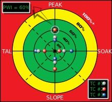
A graphical representation of the Process Window Index for a thermal profile.
In the electronics manufacturing industry, a statistical measure, known as the Process Window Index (PWI) is used to quantify the robustness of a thermal process. PWI helps measure how well a process "fits" into a user-defined process limit known as the Specification Limit.Each thermal profile is ranked on how it "fits" in a process window (the specification or tolerance limit).
The center of the process window is defined as zero, and the extreme edge of the process window as 99%.A PWI greater than or equal to 100% indicates that the profile does not process the product within specification. A PWI of 99% indicates that the profile processes the product within specification, but runs at the edge of the process window. A PWI of 60% indicates a profile uses 60% of the process specification. By using PWI values, manufacturers can determine how much of the process window a particular thermal profile uses. A lower PWI value indicates a more robust profile.
For maximum efficiency, separate PWI values are computed for peak, slope, reflow, and soak processes of a thermal profile. To avoid the possibility ofthermal shock affecting the output, the steepest slope in the thermal profile must be determined and leveled. Manufacturers use custom-built software to accurately determine and decrease the steepness of the slope. In addition, the software also automatically recalibrates the PWI values for the peak, slope, reflow, and soak processes. By setting PWI values, engineers can ensure that the reflow soldering work does not overheat or cool too quickly.
Post time: Mar-01-2022


